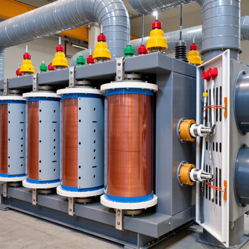
| Transformer Type | Cast-resin or VPI/open-wound construction | Electrical energy is transferred between primary and secondary windings by electromagnetic induction. Dry type units use air or solid insulation instead of liquid dielectric fluid. | Reduces liquid-leakage and fire-related risks while allowing indoor installation in many applications. | Cast-resin designs generally provide strong moisture and contamination resistance; ventilated designs require a suitably clean and dry installation environment. |
| Rated Power | Common distribution range: 15 kVA to 2,500 kVA | The kVA rating indicates the apparent power the transformer can deliver continuously under specified cooling, ambient, and temperature-rise conditions. | Determines the maximum continuous load capacity and influences physical size, losses, and installation cost. | Select a rating above the calculated demand and allow for motor starting, nonlinear loads, future expansion, and required overload capability. |
| Operating Frequency | 50 Hz or 60 Hz | The alternating current frequency determines the relationship between voltage, turns, core area, and magnetic flux density. | Operating at a lower frequency than the design frequency can increase core flux and cause saturation, excessive current, noise, and heating. | Use a transformer designed for the actual system frequency. A 60 Hz transformer should not automatically be applied at 50 Hz without confirmation. |
| Primary Voltage | Typically 2.4 kV to 35 kV for medium-voltage dry type units | The primary winding receives the supply voltage and creates the alternating magnetic flux in the core. | Determines winding insulation requirements, clearances, termination design, and available short-circuit withstand. | Verify system voltage, highest system voltage, tap range, connection configuration, and required impulse withstand level. |
| Secondary Voltage | Common low-voltage outputs include 208 V, 240 V, 400 V, 415 V, 480 V, and 600 V | The secondary winding converts the magnetic flux into the required utilization voltage according to the turns ratio. | Determines load compatibility, secondary current, conductor size, and voltage-drop performance. | Match the secondary voltage to the actual load and account for regulation, tap settings, motor starting voltage drop, and distribution distance. |
| Voltage Ratio | Approximately equal to the primary-to-secondary turns ratio | For an ideal transformer, V1/V2 is approximately equal to N1/N2, where V is voltage and N is the number of turns. | Controls voltage conversion. Winding resistance and leakage reactance cause the actual loaded secondary voltage to differ slightly from the no-load value. | Check the stated ratio at the nominal tap and confirm whether the specified voltages are line-to-line or line-to-neutral. |
| Core Material | Grain-oriented electrical steel, commonly CRGO | Laminated steel sheets guide the alternating magnetic flux while reducing eddy-current paths through insulation between laminations. | Core material and processing influence no-load loss, magnetizing current, temperature rise, and audible sound. | Lower-loss steel can improve efficiency, but core quality, joint design, clamping, and operating flux density are also significant. |
| Core Flux Density | Often designed around 1.4 T to 1.7 T at rated voltage and frequency | Flux density is controlled by applied volts per turn, frequency, and core cross-sectional area. | Higher flux density can reduce material volume but increases the risk of saturation, no-load current, vibration, and core loss. | Evaluate the specified volts-per-hertz condition, especially where supply voltage or frequency may vary. |
| Core Loss | Usually specified as no-load watts or watts per kVA | Core loss consists mainly of hysteresis and eddy-current losses and occurs whenever the transformer is energized, even without load. | Contributes to continuous energy consumption and heating during periods of low or zero load. | Compare guaranteed no-load loss values when the transformer will remain energized for long operating periods. |
| Winding Conductor | Copper or aluminum | Current flows through the primary and secondary windings, producing the magnetic field and transferring power through the core. | Conductor material, cross-sectional area, and arrangement affect resistance loss, temperature rise, mechanical strength, and dimensions. | Copper generally provides higher conductivity per unit area; aluminum can reduce mass and cost when correctly designed and terminated. |
| Winding Configuration | Delta, wye, zigzag, or other specified three-phase connections | The connection determines phase relationships, neutral availability, triplen-harmonic behavior, and grounding options. | Affects system protection, fault behavior, compatibility with loads, and the ability to supply line-to-neutral loads. | Specify the vector group, phase displacement, neutral grounding arrangement, and required secondary neutral capacity. |
| Taps | Typical off-circuit tap range: approximately ±2 × 2.5% or ±5% | Taps change the effective number of turns to compensate for supply-voltage variation while the transformer is de-energized. | Helps maintain the desired secondary voltage across a range of primary supply conditions. | Off-circuit taps must not be changed while energized. Confirm tap location, operating procedure, and voltage limits. |
| Insulation Thermal Class | Common classes: Class F, 155°C; Class H, 180°C | The thermal class indicates the maximum temperature capability of the insulation system under defined conditions. | Higher thermal class can provide greater thermal margin, but it does not automatically permit unlimited loading. | Thermal class is different from allowable temperature rise. The nameplate temperature-rise rating must also be considered. |
| Temperature Rise | Common values include 80 K, 100 K, or 150 K, depending on design and standard | Temperature rise is the winding or enclosure temperature increase above the specified ambient reference at rated load. | Lower temperature rise generally improves insulation life, overload margin, and efficiency but may require more active material and cooling surface. | Check the applicable standard, ambient temperature, altitude, ventilation, and whether the rating is based on average or hottest-spot temperature. |
| Ambient Temperature | Often based on a 40°C maximum ambient, subject to the applicable standard | Heat produced by winding and core losses must be transferred to the surrounding air without exceeding insulation limits. | Higher ambient temperature reduces available thermal margin and may require derating or improved ventilation. | Account for room temperature, solar or process heat, airflow, enclosure heat retention, and installation altitude. |
| Insulation Coordination | Specified by rated insulation level and impulse withstand level | Insulation barriers between turns, windings, core, and ground must withstand normal operating voltage and transient overvoltages. | Determines resistance to switching surges, lightning impulses, partial discharge, and electrical breakdown. | Do not infer dielectric strength from thermal class alone. Confirm power-frequency withstand and lightning impulse withstand values for the system voltage. |
| Partial Discharge | Specified limit depends on design, voltage class, and test standard | Partial discharge is a localized electrical discharge that does not completely bridge the insulation between conductors. | Low, stable partial-discharge performance supports long-term reliability in medium-voltage insulation systems. | Require a defined test method, test voltage, acceptance limit, and test report when selecting medium-voltage cast-resin equipment. |
| Impedance | Often approximately 4% to 8% for distribution transformers, depending on rating and design | Leakage reactance and winding resistance limit fault current and produce voltage drop under load. | Higher impedance reduces available short-circuit current but can increase voltage regulation and motor-starting voltage drop. | Coordinate impedance with upstream and downstream protective devices, parallel operation requirements, and motor starting performance. |
| Voltage Regulation | Typically a few percent at rated load, depending on power factor and impedance | Regulation represents the change in secondary voltage between no-load and load conditions at a specified power factor. | Lower regulation helps maintain stable load voltage and reduces the risk of undervoltage during heavy loading. | Evaluate regulation at the actual load power factor, not only at unity power factor. |
| Efficiency | Often above 97% for medium and large distribution units at favorable loading | Efficiency equals output power divided by input power. Losses include core loss, winding I²R loss, stray loss, and auxiliary fan power if fitted. | Higher efficiency reduces operating cost and heat generation over the transformer’s service life. | Compare efficiency at the expected load profile because core loss is relatively constant while winding loss varies approximately with current squared. |
| Cooling Method | AN: air natural; AF: forced air | Natural convection removes heat through air movement. Fans increase airflow and can provide a higher temporary or continuous capacity rating when permitted. | Forced-air cooling can increase available output but adds fan energy use, noise, maintenance, and control-system requirements. | Confirm whether the kVA rating is for AN operation, AF operation, or both, and verify fan redundancy for critical installations. |
| Harmonic Loading | Consider K-factor or harmonic derating for nonlinear loads | Triplen harmonics can accumulate in neutral or delta paths, while harmonic currents increase eddy-current and stray losses in windings and structural parts. | Excessive harmonics can cause overheating, audible noise, neutral-current stress, and reduced usable capacity. | Analyze the load spectrum for variable-frequency drives, UPS systems, rectifiers, data-processing equipment, and LED power supplies. |
| Short-Circuit Withstand | Specified for a defined duration, commonly 2 seconds under applicable standards | Windings and clamping structures must withstand electromagnetic forces produced by high fault current without unacceptable deformation. | Improves post-fault reliability and helps preserve winding insulation and clearances. | Coordinate the transformer impedance and protective-device clearing time with the available system fault current. |
| Enclosure Protection | Common indoor examples include IP00, IP20, or higher levels as required | The enclosure limits access to energized parts and protects the transformer from solid objects, dust, and water according to its ingress-protection rating. | A more protective enclosure improves personnel safety and environmental resistance but can restrict ventilation and increase temperature rise. | Choose the enclosure according to access control, dust, moisture, corrosion, ventilation, and local installation requirements. |
| Altitude Derating | Often requires review above approximately 1,000 m elevation | Reduced air density decreases natural and forced-air cooling effectiveness and may reduce external insulation withstand capability. | Can require lower loading, larger clearances, stronger insulation coordination, or enhanced cooling. | Provide installation altitude during specification and request the manufacturer’s applicable correction factors. |
| Sound Level | Typically specified in dB(A) at a defined distance and operating condition | Core magnetostriction, winding vibration, enclosure resonance, and cooling fans contribute to audible noise. | Important for offices, hospitals, residential buildings, and other noise-sensitive locations. | Use the specified test method and distance when comparing values. Room acoustics can make installed sound levels differ from factory measurements. |
| Expected Service Life | Often several decades when correctly loaded, ventilated, and maintained | Insulation aging is strongly affected by sustained temperature, moisture, contamination, mechanical stress, and electrical transients. | Lower operating temperature and clean, dry conditions generally slow insulation aging and improve reliability. | Maintain clearances, inspect terminals and fans, clean ventilation paths, monitor temperature, and avoid repeated overload operation. |